Archive for September 2016

Electromagnetism- O Level Physics

ELECTROMAGNETISM!

Magnetic effect of current:
Remember that a current-carrying conductor produces a magnetic field around it. If the current direction is reversed, the magnetic field direction will be reversed too, as shown in the diagram above.


A dot in the wire, as shown above, shows the current coming out of the plane whereas a cross in the wire shows the current moving into the plane.
Now how to determine the direction, shown above, of the magnetic field?

The right hand grip rule! Grip the wire with your right hand in such a way that the thumb is pointing to the direction of the current. The curl of your fingers, in turn, will show the direction of the magnetic field. Easy?

The strength of the magnetic field in a long, straight current carrying wire depends on
        the magnitude of the current. A larger current will produce a stronger magnetic field around the wire.
        the distance from the wire. The strength of the field decreases as you move further out.

Magnetic field pattern around a flat coil:

The direction of the field can be determined by the Right Hand Grip Rule. Grip the wire at one side of the coil with your right hand, with thumb pointing along the direction of the current. Your other fingers will be pointing in the direction of the field. Then do the same with the other side of the coil.
Plane view of the flat coil:

In a flat coil the strength of the magnetic field is closer in the centre of the wire as you can see in the diagram above (closer field lines). To increase the strength,
        increase the current ,
        increase the number of turns of the coil.

Magnetic field pattern of a solenoid:
A solenoid is a long coil made up of a numbers of turns of wire. The magnetic field of a solenoid resembles that of the long bar magnet, and it behaves as if it has a North Pole at one end and a South Pole at the other.

You would have noticed that it’s equal to increasing the turns of wire of flat coil
To determine the poles in this case, again, apply right hand rule as shown below. The fingers point towards the current direction while the thumb will show North pole direction, as shown:


The strength of the magnetic field in this case can be increased by
        Increasing the current,
        Increasing the number of turns per unit length of the solenoid,
        Using a soft-iron core within the solenoid.


Force on current carrying conductor:
Now if you place the same current carrying wire in a magnetic field, the wire will experience a force. The force is experienced due to the interactions between the two magnetic fields (Which two? The one which we learned is produced by the current carrying wire itself, and the one in which it is placed) which produces a force on the conductor.
The direction of the force should be known, and this can be found using the Fleming’s left hand rule as shown in the diagram:

Notice that the fore finger, middle finger and the thumb are perpendicularly to each other. The forefinger points along the direction of the magnetic field, middle finger points in the current direction and the thumb points along the direction of the force.
The strength of the force can be increased by
1.       Increase the current
2.       Using a stronger magnet.
And the force direction can be controlled easily. It can be reversed by reversing the direction of the current or the magnetic field.
 Now let’s see how exactly a force is experienced on the current-carrying conductor when placed in a magnetic field. The interaction between the two magnetic fields is as shown below:

We know that the field lines will always be from North to South. The direction of the current is shown by the cross, which is into the plane. Now apply the left hand rule and you’ll get the direction of the force which is 1 in the diagram.

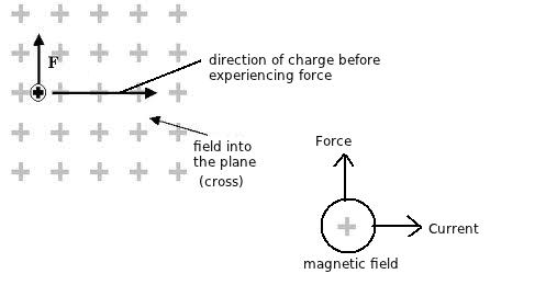
Force on a moving charge in magnetic field:
Now if we consider a charge entering a magnetic field with direction into the plane, the direction of current will be the convectional current direction i.e. from positive to negative (the direction of current is shown). Now if you apply left hand rule, you’ll get the direction of force it will experience, which will be upwards.


Forces between two parallel current-carrying conductors:
If two parallel wires are placed together, we know they will generate a magnetic field around them, right? The wires will experience a force. Why? Let’s see!


If you right hand rule on the current carrying wires, you’ll get the direction of the fields around them. Now if the direction of the current in both wires is the same, they will attract. If, however, the direction is opposite, they will repel. This is because the field direction in the wires with same current direction will be the same. See the diagram carefully and draw it yourself, you’ll understand how this happens.

Force on current-carrying rectangular coil in a Magnetic field:

If a current carrying coil is placed in a magnetic field (As shown in diagram above), a pair of forces will be produced on the coil. This is due to the interaction of the magnetic field of the permanent magnet and the magnetic filed of the current carrying coil.

The direction of the force can be determined by Fleming's left hand rule. Since the current in both sides of the coil flow in opposite direction, the forces produced are also in opposite direction. The 2 forces in opposite direction constitute a couple which produces a turning effect to make the coil rotate.

This phenomenon is used in a d.c. (direct current) motor. What does an electric motor do? It simple converts electric energy to kinetic energy. The d.c. motor consists a rectangular coil of wire placed between 2 permanent magnets. The coil are soldered to a copper split ring known as commutator. 2 carbon brushes are held against the commutator.
This is shown below:

The function of the brush is to conduct electricity from the external circuit to the coil and allow the commutator to rotate continuously (since the brush is of carbon, it conducts electricity).
The function of the commutator is to change the direction of the current in the coil and hence change the direction of the couple (the 2 forces in opposite direction) in every half revolution. This is to make sure that the coil can rotate continuously.


Posted in , , | 25 Comments

Electromagnetic Waves

ELECTROMAGNETIC WAVES!
Introduction:
Hey everyone! How are you? Okay so this is a really short topic which we are going to study today: Electromagnetic waves. Its more of having it on fingertips than grabbing the concept. Let’s get started!

Definition:
Electromagnetic waves belong to the electromagnetic spectrum. Light is a part of this spectrum. And the only part of spectrum that we are able to see is light. The rest of it, like radio rays, are not visible to us.

Here’s the electromagnetic spectrum:

Gamma rays have the shortest wavelength and the highest frequency while radio waves have the longest wavelength and the lowest frequency.

Properties of electromagnetic waves:
        Electromagnetic waves are transverse waves. They are electric and magnetic fields that oscillate at 90° to each other.
        They transfer energy from one place to another.
        They can travel through vacuum (do not require any medium to travel)
        They travel at 3.0 x 10⁸  metres per second in vacuum. They will slow down when travelling through water or glass.
        The wave equation is applicable here too.
        They obey the laws of reflection and refraction.
        They carry no electric charge (they are neither positively or negatively charged)
        Their frequencies do not change when travelling from one medium to another. Only their speeds and wavelength will change.

Just memorise these properties and you’re done!

The only left for you to do is google the uses of these waves and memorise them. You should know at least two uses of each wave. Like ultraviolet waves are used in sunbeds and in sterilization of medical equipment.


Posted in , | Leave a comment

Electromagnetic Induction (O level Physics)

ELECTROMAGNETIC INDUCTION!


Electromagnetic Induction:
When a magnet is moved into and out of the solenoid, magnetic flux is being cut by the coil. The cutting of magnetic flux by the wire coil induces an e.m.f in the wire. When the solenoid is connected to a closed circuit, the induced current will flow through the circuit.
The direction of the induced current and the magnitude of the induced e.m.f due to the cutting of the magnetic flux can be determined from Lenz's Law and Faraday's Law.

Faraday’s Law:
Faraday’s law states that whenever flux linking to a conductor changes, an e.m.f. is induced in the conductor, perpendicular to flux and direction of motion. The rate of change of flux is proportional to the e.m.f. induced. These are the really scientific terms for the law. What is flux anyway? Flux is basically the amount of magnetic field passing through a given surface.

Lenz’s Law:
The direction of the induced e.m.f., and hence the induced current in a closed circuit, is always such that its magnetic effect opposes the motion or change producing it.


The diagram shows that when a magnet is moved into the solenoid, the galvanometer deflects, which means there must be current flowing. Presence of current means that an induced e.m.f. is generated in the circuit which drives a current round the closed circuit.
If the magnet remains stationary, there won’t be any current passing and no deflection in galvanometer.

A.c. generator:

The a.c. generator transforms mechanical energy into electrical energy, hence it generates electricity.  Generator can be modified to an a.c generator by replacing its commutators with two (separate) slip rings. The two slip rings rotate in tandem with the armature (the rectangular coil). Carbon brushes connect the armature to the external circuit. The armature is initially at the vertical position. No magnetic flux is cut and hence no induced current exists.

When the armature rotates, the change in magnetic flux increases and the induced current increases until its maximum value at the horizontal position. The direction of the induced current can be determined from Fleming's Right Hand rule. Fleming's Right-Hand Rule is used to determine the direction of the induced current that flows from the wire when there is relative motion with respect to the magnetic field.


As the armature continues on its rotation, the change in magnetic flux decreases until at the vertical position, no induced current exists.
Now upon reaching the horizontal position again, the induced current is maximum, but the direction of the induced current flowing through the external circuit is reversed.

The direction of the induced current (which flows through the external circuit) keeps changing depending on the orientation of the armature. This induced current is also known as alternating current. The current is positive (+) in one direction and negative in the other (-). The smooth rings play an important role in the generation of alternating current.


The diagram shows the front view of the armature (A and B shown in the previous diagram). This graph is for one revolution of the coil.
The frequency f of the rotation is related to its period T by the equation:
f = 1 / T
From this equation, we can see that doubling the frequency f means halving the period T.
To increase the induced e.m.f. of an a.c. generator, we can
        increase the number of turns on the coil,
        increase the frequency of rotation of coil,
        use stronger permanent magnet,
        use a soft-iron core.

Transformers:
What is transformer? A transformer is a device that is used to raise or lower down the potential difference of an alternating current. It either increases or decreases the p.d. of an a.c. supply. This is how it looks like:

It consists of the primary coil, the core and the secondary coil.
        The primary circuit is the circuit that connected to the input energy source. The current, potential difference and coil (winding) in the primary circuit are called the primary current (Ip), primary potential difference (Vp) and primary coil respectively.
        The core is the ferromagnetic metal wound by the primary and secondary coil. The function of the core is to transfer the changing magnetic flux from the primary coil to the secondary coil.
        The secondary circuit is the circuit that connected to the output of the transformer. The current, potential difference and coil (winding) in the secondary circuit are called the secondary current (Is), secondary potential difference (Vs) and secondary coil respectively.

Now this is how a transformer works:
1.       A transformer consists of a primary coil and a secondary coil wound on a soft iron core.
2.       When an alternating current flows in the primary coil, a changing magnetic flux is generated around the primary coil.
3.       The changing magnetic flux is transferred to the secondary coil through the iron core.
4.       The changing magnetic flux is cut by the secondary coil, hence induces an e.m.f. in the secondary coil.
5.       The magnitude of the output voltage can be controlled by the ratio of the number of primary coil and secondary coil.
In a step-up transformer, the e.m.f. of the secondary coil is greater than the e.m.f. of the primary coil. Similarly, in a step-down transformer, the e.m.f. of the secondary coil is less than the e.m.f. of the primary coil. It can be shown that:
Vs / Vp = Ns / Np
where Vs is the secondary output voltage, Vp is the primary input voltage, Ns are the number of turns in the secondary coil and Np are the number of turns in the primary coil.
Ns / Np is called the turns ratio.

Power transfer in a transformer:
Here we’ll consider an ideal transformer that is 100 % efficient, so power of the primary coil is fully transferred to the secondary coil. Hence, the Principal of Conservation of energy is applied, from where the power in the primary coil = power in the secondary coil.
We know the formula P = VI, right?
So we can say that:
(Ip) (Vp) = (Is) (Vs)
where Ip is current in the primary coil, Is is current in the primary coil, Vp is the primary input voltage and Vs is the secondary output voltage.

Now coming to a non-ideal transformer, there will always be power loss, i.e. the efficiency is less than 100 %.
Efficiency = (Output power / Input power ) x 100%

Converting a.c. to d.c.:
We know that the electricity supplied to our homes is in the form of a.c.. But we also know that many appliances require d.c.. So how is a.c. converted into d.c.?
The use of diode is the solution to this! A diode is a semiconductor device that allows a current to flow easily in one direction only. Simple.


When the diode is connected as in Figure A above, where the anode wire is connected to the positive pole and the cathode connected to the negative pole of battery, we say that forward biased diode. A diode will only conduct electricity (turn on a light) when given forward bias.
When a diode is connected with reversed polarity as shown in Figure B, where the cathode wire is connected to the positive pole and the anode connected to the negative pole of battery, we say that reverse biased diode . A diode will not conduct electricity (turn off a light) when given reverse bias.

Half-wave rectification:

Electrical current is supplied to the circuit is an alternating current generated by a transformer. During the positive half cycle of AC, diodes are forward biased so current can flow. Current that flows through the diode to the load (RL) and back toward the transformer. Then the negative AC half cycle, diode does not conduct electric current, because given the reverse bias.
Waveform of the current, then, is as shown below:

Full-wave Rectification:

This is the circuit used for full-wave rectification. The four diodes are connected in series. During the positive half cycle of the input voltage, diodes D1 and D2 will conduct, while D3 and D4 will remain off. The current will take the path ABDEF.
Now during the negative half cycle of the input voltage, diodes D1 and D2 will remain off. The current will follow the path FECDBA.

Cathode-Ray Oscilloscope:

Shown in the diagram is a simple cathode ray oscilloscope.
The device consists mainly of a vacuum tube which contains a cathode , anode , grid , X & Y-plates, and a fluorescent screen . When the cathode is heated (by applying a small potential difference across its terminals), it emits electrons (this process is called thermionic emission). Having a potential difference between the cathode and the anode (electrodes), accelerate the emitted electrons towards the anode, forming an electron beam, which passes to fall on the screen.

When the fast electron beam strikes the fluorescent screen, a bright visible spot is produced. The grid, which is situated between the electrodes, controls the amount of electrons passing through it there by controlling the intensity of the electron beam. The X & Y-plates, are responsible for deflecting the electron beam horizontally and vertically.

The front panel of the CRO looks like this:


The Y-gain of the CRO amplifies the Y-deflection. Amplifying circuits are built into the CRO so that small input voltages are amplified before they are applied to the Y-plates.
Time-base controls the speed at which the electron beam sweeps across the screen horizontally from left to right.

The settings of the CRO are set, for example time base is set at 0.5 ms/div (0.5 millisecond per division) and the Y-gain is set at 1 V/div (1 volt per division).
And this is how the trace will look like:


Here you can be asked to find the frequency and the peak voltage.
We know that frequency f is f = 1 / T.
How many divisions across the  x-axis is the wave covering? It’s almost five.
So T = 0.5 * 5 = 2.5 ms
For frequency, we need to change it to seconds.
Now for the peak voltage, the wave is covering two divisions, so it will be V = 1 * 2 = 2V.


Task: Find more questions on CRO for practice.

Posted in , | 27 Comments

D.C. Cicrcuits

D.C. CIRCUITS!
Introduction:
Hey again everyone! Hope you all are good. Today we are going to study about D.C. Circuits, D.C. is the abbreviate for direct current. In this tutorial, we’ll study how the arrangement of an electric circuit will affect the electrical properties like charge, current, e.m.f., p.d. and resistance. Ready?

Series Circuit:

The diagram shows a series circuit. All bulbs and ammeters are connected in series. Do you note that all ammeters are recording the same value? Yeah so here we are: current at any point in a series circuit is the same, no matter how much load you put in. In both bulbs above, same amount of current is flowing.

Take a look at the above circuit, it has the same battery and same bulb (only one this time though) and the ammeter is still giving the same reading. Hence, load doesn’t affect the current value in a series circuit. Easy? Let’s move on!


Potential Difference across a series circuit:

Now in the above diagram, two resistors are connected in series. We know that current will remain same at each point, only the voltage will change. To find the e.m.f. of the battery, simply add up all the voltages in the series circuit, that is:
V (e.m.f. of battery) = V1 + V2
So in scientific terms, we can say that in a series circuit, the sum of potential difference across each component is equal to the potential difference across the whole circuit (e.m.f.).

Resistance in a series circuit:
Coming to the resistance in a series circuit, consider the same circuit.

The resistance of each resistor is R1 and R2. We learned the formula V = IR in the tutorial on current electricity. So according to this, p.d. across R1 is V1 is V1 = I R1 and that across R2 is      V2 = I R2.
We know that
V = V1 + V2
V = IR1 + IR2
      = I (R1 + R2)

Therefore V / I = R1 + R2.
From the above derivation we can see that the combined resistance R  is the sum of all the resistors in the circuit. Hence in a series circuit, the combined resistance is the sum of all the resistances.


Q1. Determine the current in the ammeters A1 and A2.


Hint: The current in a series circuit is same and remember how the total resistance is calculated in series.

Parallel Circuits:
The most simple explanation can be: in a parallel circuit, there is more than one path through which electric current can flow. And as we learned that in a series circuit, current all around the circuit remains the same. In parallel its different. Take a look at the circuit below:

We can see from the circuit diagram that each lamp has its own branch. The three lamps are in parallel, so this is a parallel circuit. There are junctions between each branch which are represented by the black dots.
If we set this circuit up and connect ammeters as shown, we find that:
 A1 = A2 + A3 + A4
In other words, the currents add up. An important rule for all parallel circuits is: the currents in each branch add up to the total current.
More scientifically, in a parallel circuit, the sum of individual currents in each of the parallel branches is equal to the main current flowing into and out of the parallel branch.


P.d. across a parallel circuit:
P.d. in a parallel circuit is more like current in series: it remains same!

In the circuit above, the p.d. shown on each voltmeter is the same as the battery voltage.

Resistance in a parallel circuit:

The diagram shows exactly how combined resistance of resistors in parallel can be found.

Q2. Calculate the total resistance in the following circuit where
R1 = 2 Ω, R2 = 4 Ω and R3 = 6 Ω.

There are two advantages of connecting bulbs in parallel. Firstly, they glow more brightly in parallel because with the same e.m.f. of the battery, each bulb in series gets less voltage than the power e.m.f. while in parallel, all bulbs will get the same e.m.f. as we just learnt. More voltage means more current according to V = IR and hence, brighter the bulb! Secondly, in parallel, if one bulb goes out, the other continues to glow normally. While in series, when one bulb goes out, the circuit breaks and then obviously, other bulbs won’t light up.

Differences between series and parallel (Summary):
Okay let’s just quickly revise the differences between series and parallel circuits.
        In series, current remains same at every point while voltage varies. In parallel, current varies while voltage remains the same at every point.
        To find the total resistance in series just simply add up the resistances, and for parallel apply the formula R (total) = (1 / R1) + (1 / R2) + (1 / R3) …
        Now in series, the sum of all p.d.s is the e.m.f. Try to remember what we learned about p.d. in the tutorial on current electricity.
        Here’s a new point: to find the P.d. of any load (a resistor for instance) for which you know the resistance, the total resistance of the circuit and the total voltage, apply the formula
P.d. = ( R / Rtotal) x Vtotal.

Potential Divider:
A potential divider is not as complicated as its name sounds. It is simply a circuit with resistors arranged in series. We know that the potential difference across each resistor in a series arrangement changes according to the resistance of the resistor.Hence, we can divide a main voltage into two voltages.

Take a look at a simple potential divider circuit above. Vin is the e.m.f. supplied by the cell which has been divided into two potential differences across each resistor R1 and R2. The Vout across R1 is then used to drive another part of circuit.
We can find the current through the resistors R1 and R2 by using:
I = ( V / R1 + R2 )
Hence the potential difference Vout across R2 is given by:
 Vout =  IR2 = ( V / R1 + R2 ) x  R1

Now find the Vout in the following diagram:

Here’s how you’ll solve it:


Answers:
Q1. 0.5 A
Q2. 1.1 Ω


Posted in , , | 14 Comments

Current Electricity (O Level Physics)

CURRENT ELECTRICITY!
Introduction:
Welcome back everyone! Hope you are all good. Today we’ll learn about current electricity. We have studied in the tutorial on static electricity that insulators and conductors become charged when electrons are added or removed from them. We know that these electrons are stationary, but what will happen if these electrons are provided with a conducting path? The electrons will start to flow, and moving  electrons produce electric current.

Electric Current:
As we just saw, electric current is produced when electrons flow. These electrons always flow from a negatively charged to a positively charged end. This is the electron flow.
Now coming to the convectional current, in the previous days it was assumed that current flows from positive to negative end and it is widely held today. This is called the convectional current flow. The diagram below makes it clearer.

Electric current (I) is a measure of the rate of flow of electric charge (Q) through a given cross section of a conductor.
Such that:
I = Q / t
The SI unit of current is ampere (A). An ammeter is used to measure current.
Now before moving on, you should all be aware of how a simple circuit looks like.

In the circuit shown above, it consists of:
1.       a source of electromotive force that drives electric current (e.g. battery)
2.       a load on which moving charges can do a useful job (e.g. a bulb)
3.       conductors to connect the components together (e.g.  copper wire)
4.       switch to open or close a circuit.

Task: Google the symbols used in circuit diagram for different apparatuses.

Electromotive Force and Potential Difference:
Electromotive force (e.m.f) is the energy required to move a unit positive charge from one end of the circuit to another. Such that:
E = W / Q
where E is the e.m.f. of the power supply, W is the amount of electrical energy converted from electrical to non-electrical forms (work done) and Q is the amount of charge. The SI unit for e.m.f. is Joule per Coulomb or volt (V).
Remember that e.m.f. is the movement of charge through the entire circuit.

The diagram above shows the voltage calculated of the cell, and as cell is providing voltage to the entire circuit, it is hence e.m.f.
Now, potential difference (p.d.) is the amount of electrical energy consumed to move a unit positive charge from one point to another in an electrical circuit. Such that:
V = W / Q
where V is the p.d., W is the electrical energy converted to other forms and Q is the amount of charge. The SI unit for this is the same as that for e.m.f. and that is volt (V).

The diagram shows how p.d. can be calculated across the bulb (between two points).
Resistance:
Resistance, as the name suggests, is the measure of how difficult it is for an electric current to pass through a material, copper wire let’s say. So it is basically the restriction (resistance) of a material to the free moving electrons in the material. If you compare it with the friction in moving objects, it’s quite correct.
Now in more scientific terms, resistance R of a component is the ratio of the potential difference across it to the current I flowing through it, such that:
R = V / I
where R is resistance, V is the p.d. across the component (note that across a component, that is, between two points, it’s p.d. and not e.m.f.) and I is the current flowing through it.
The SI unit of resistance is ohm (Ω).

Resistance is measured using a conductor called resistor. Resistors are of two types: fixed and variable (rheostats). Now you can tell exactly from the name what these are, right? Fixed resistors have a fixed value while variable resistors can vary the resistance and are used in circuits to vary current.

Ohm’s Law:
Ohm’s Law states that the current passing through a metallic conductor is directly proportional to the p.d. across the ends, provided the physical conditions (such as temperature) are constant.
Such that:
I α V
where I is current and V is p.d.
and this drives us to the formula which we have already learned, i.e.
V / I = constant = R
From this, we can make another conclusion that resistance of a metallic conductor remains constant under steady physical conditions, and such conductors which obey Ohm’s law are called ohmic conductors. For ohmic conductors, I-V graph has a constant gradient (i.e. inverse of resistance), as shown below:

Not all conductors obey Ohm’s Law, such conductors are non-ohmic conductors. The resistance of such conductors can vary, but how do we differentiate? The I-V graphs of different conductors can help us differentiate.
For example, for a filament lamp, when the p.d. across the lamp increases, the current does not increase proportionally. The graph below makes it clearer:

The deviation of I-V graph from straight line is due to increase in the resistance of the filament with temperature. The graph is straight line in initial stage because the increase in resistance of the filament with the temperature due to small current is not appreciable. As the current is further increased, the resistance of the filament continues to increase due to rise in temperature (Though the gradient is decreasing, how can we say that the resistance is increasing? That’s because slope is the inverse of gradient in this case). How is the temperature rising? It’s rising because as the bulb remains on for a long time, more energy is dissipated to heat energy.
Task: Google other non-ohmic conductors and find out how their resistance varies in an I-V graph.

Resistivity:
Apart from temperature, there are other factors as well on which R depends. As for temperature, the higher the temperature of metallic wire, the larger the resistance.
The resistance depends on
1.       the length l of the wire,
2.       the cross-sectional area A or thickness of the wire, and
3.       the type of material.
To memorize how these factors affect the resistivity of the conductor, memorize the following formula:
R = p (l / A)
where R is the resistance, p (a constant) is the resistivity, l is the length and A is the cross-sectional area of the wire.
This shows that R α l and that R α 1 / A.
So now me have made it quite easy: as R is directly proportional to length, the longer the length of the wire, the greater is its resistance, and as R is inversely proportional to cross-sectional area of wire, the greater is its cross sectional area, the lower is its resistance.


Now for the type of material, every material has a different resistance. For example, the resistance  of silver is 1.6 x 10⁻⁸ Ω while that of graphite is 3000 x 10-8 Ω.

Posted in , | 24 Comments